Importing Kismet captures into Google Maps

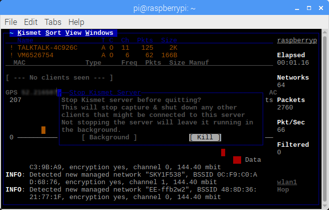
Having captured a few WiFi hot spots while driving around I wanted to export these hotspots to a KML file that I could then import into Google Maps. There are applications and scripts to do this but I decided to have a go a creating something myself. As I am currently learning Python and in my opinion the best way to learn a new language is by doing then Python was my first choice for this. I am by no means a Python expert and there will be better ways of doing this I am sure.

The first step is to open the Kismet XML file for parsing. The simplest way I found was to use an ElementTree.

import sys
import xml.etree.ElementTree as Etree

# Open the XML file
tree = Etree.parse("test.netxml")
root = tree.getroot()

Next we need to parse the child nodes looking specifically for the “wireless-network” tag. From there we can parse each sub element to extract the information we are interested in. Including the SSID, MAC address, location etc.

for child in root:
    # If new network entry
    if child.tag == "wireless-network":
        essid = ""
        bssid = ""
        encryption = []
        gpslat = ""
        gpslng = ""
        # Iterate through child elements
        for element in child:
            # SSID element
            if element.tag == "SSID":
                # Interate through each sub element
                for subelement in element:
                    # Found encryption type add it to the list
                    if subelement.tag == "encryption":
                        encryption.append(str(subelement.text))
                    # Found SSID save it
                    elif subelement.tag == "essid":
                        essid = str(subelement.text)
            # BSSID element contains MAC address save it
            if element.tag == "BSSID":
                bssid = str(element.text)
            # Location fix element
            if element.tag == "gps-info":
                for gps in element:
                    # Extract latitude
                    if gps.tag == "avg-lat":
                        gpslat = str(gps.text)
                    # Extract longitude
                    if gps.tag == "avg-lon":
                        gpslng = str(gps.text)
            # Sort encryption list
            encryption.sort()

With the input file parsed we move on to exporting the results to a KML file. For this I used the SimpleKML python library. SimpleKML makes working with KML files a breeze.

import simplekml

# Create an instance if simplekml
kml = simplekml.Kml()
# Add a new point
kml.newpoint(name=essid, description=bssid + " " + 
            ' '.join(encryption), coords=[(gpslng, gpslat)])
# Now save it
kml.save("output.kml")

That’s the basics covered. Time to add some features. One thing I wanted was to be able to filter hotspots found within a specific radius of a given point. For instance if you only wanted to save hotspots within a mile of your house you could enter you home location and set a search radius of one mile. The resulting KML file would then only contain hotspots that fell within that radius. For this we can use the Haversine formula. The Haversine formula determines the great-circle distance between two points on a sphere (in this case the earth) given their longitudes and latitudes. There is also happens to be a nice little Haversine python library.

from haversine import haversine

home = (45.7597, 4.8422)
dest = (48.8567, 2.3508)
distance = haversine(home, dest, unit='mi')
if distance > 1.0:
    print ("Greater than 1.0 miles!")

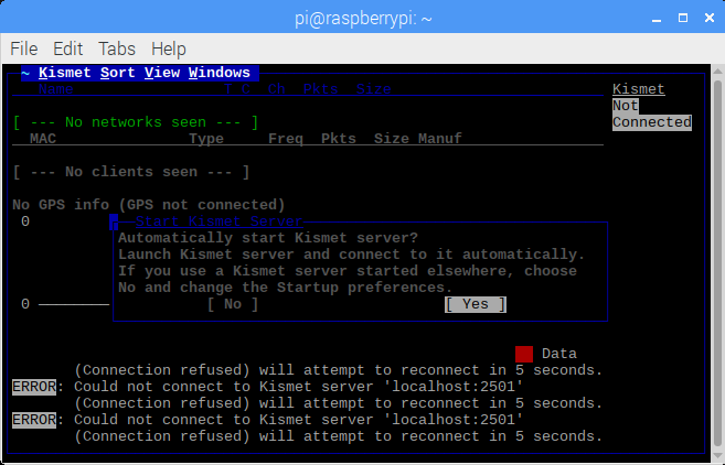
More features were then added including/excluding specific SSID’s, specifying certain authentication types, specifying the output file etc all of which are passed as arguments to the script.

My resulting netxml2kml script can be seen below:-

#!/usr/bin/env python3
import sys
import xml.etree.ElementTree as Etree
import os.path
import simplekml
import argparse
from haversine import haversine

# python netxml2kml.py test4.netxml output.kml -r 5.0 -x 45.7597 -y 4.8422 -s
# python netxml2kml.py test4.netxml output.kml -i Raspberry -s
# python netxml2kml.py test4.netxml output.kml -e Raspberry -s
# python netxml2kml.py test4.netxml output.kml -a WEP -s

def str2bool(v):
    if v.lower() in ('yes', 'true', 't', 'y', '1'):
        return True
    elif v.lower() in ('no', 'false', 'f', 'n', '0'):
        return False
    else:
        raise argparse.ArgumentTypeError('Boolean value expected.')

parser = argparse.ArgumentParser(description='Convert Kismet Net XML to KML file.')
parser.add_argument("input_file", help="the Net XML file to be converted.")
parser.add_argument("output_file", help="the KML output file.")
parser.add_argument("-e", "--exclude", default="", help="exclude SSID string.")
parser.add_argument("-i", "--include", default="", help="include SSID string.")
parser.add_argument("-a", "--auth", default="", help="include search authentication string.")
parser.add_argument("-r", "--radius", type=float, default=0.0, help="include radius")
parser.add_argument("-x", "--lat", type=float, default=45.7597, help="start latitude")
parser.add_argument("-y", "--lon", type=float, default=4.8422, help="start longitude")
parser.add_argument("-s", "--show", type=str2bool, nargs='?', const=True, default=False, help="Show output entries.")
args = parser.parse_args()

def do_extraction(filename: str, output: str, exclude: str, include: str, auth: str, show: bool, radius: int,
                  lat: float, lon: float) -> int:
    if os.path.exists(filename) is False:
        print("Cannot find input file \"%s\"" % filename)
        sys.exit(1)
    print("Opening file \"%s\"" % filename)
    print("Saving to file \"%s\"" % output)
    tree = Etree.parse(filename)
    root = tree.getroot()
    kml = simplekml.Kml()
    print("Extracting entries...")
    found = 0
    for child in root:
        if child.tag == "wireless-network":
            essid = ""
            bssid = ""
            encryption = []
            gpslat = ""
            gpslng = ""
            for element in child:
                if element.tag == "SSID":
                    for subelement in element:
                        if subelement.tag == "encryption":
                            encryption.append(str(subelement.text))
                        elif subelement.tag == "essid":
                            essid = str(subelement.text)
                if element.tag == "BSSID":
                    bssid = str(element.text)
                if element.tag == "gps-info":
                    for gps in element:
                        if gps.tag == "avg-lat":
                            gpslat = str(gps.text)
                        if gps.tag == "avg-lon":
                            gpslng = str(gps.text)
                encryption.sort()
            valid = True
            if radius > 0.0:
                if gpslat and gpslng:
                    home = (lat, lon)
                    dest = (float(gpslat), float(gpslng))
                    dist = haversine(home, dest, unit='mi')
                    if dist > radius:
                        valid = False
            if include and essid.find(include) = 0:
                valid = False
            if auth and auth not in encryption:
                valid = False
            if valid:
                found += 1
                kml.newpoint(name=essid, description=bssid + " " + ' '.join(encryption), coords=[(gpslng, gpslat)])
                if show:
                    print(essid + "," + bssid + "," + ' '.join(encryption) + "," + gpslat + "," + gpslng)
    kml.save(output)
    print("Extracted %d entries." % found)
    return found

if __name__ == "__main__":
    ret = do_extraction(args.input_file, args.output_file, args.exclude, args.include, args.auth, args.show,
                        args.radius, args.lat, args.lon)

Mobile Wardriving Rig

I can’t quite believe it’s been over two years since I posted anything. So, apologies for that and with any luck hopefully I can improve on that and post a few more updates on recent escapades.

The last few months I have been experimenting with the Raspberry Pi for a whole host of applications. One thing I have wanted to do for some time is build a mobile Wardriving rig. For those that don’t know Wardriving is the art of scanning for Wi-Fi networks, usually from a car or other vehicle, and mapping out their locations. Basic setups would normally comprise a laptop, some means of determining your location and an external Wi-Fi adapter. I don’t fancy lumping around my laptop and figured it must be possible to achieve something similar using a Raspberry Pi. With a bit of free time on my hands I decided this would make an ideal weekend project.

My Wardriving rig running on the bench in the lab.

For anyone who wishes to build something similar this post will detail how I built mine. I’ll be honest I am not an expert on the Raspberry Pi or Linux and some of this is a learning curve for me.

All boxed up ready for deployment.

Shopping List

Before we get started on the build we are going to need a few bits of kit. The list below is what I used. I’ll be honest adding it all up it wouldn’t be cheap but fortunately I already had most of this stuff lying around. There will of course be suitable alternatives that will fit the bill, but I’ll leave that up to you.

Raspberry Pi 3 B+

If you going to build a mobile Wardriving rig using a Raspberry Pi it may as well be the latest version right.

Touch – HyperPixel 4.0

Most people would normally opt for a headless setup when building mobile wardriving rig. Then either SSH into the Pi using a laptop or mobile phone. My goal was to makes this as mobile as possible. I didn’t want to have to rely on any additional hardware. For this reason, I decided to use the HyperPixel 4.0. With a 4.0” IPS panel, 800×480 pixels, approx. 235 PPI, 18-bit colour and up to 60 FPS this is a truly excellent display. Did I mention there is also has a touch screen?

BT-708 USB GPS Receiver

To accurately determine your location we need a GPS receiver. The BT-708 USB GPS Receiver uses the UBX-G7020-KT chipset from U-Blox. I love the U-Blox range of receivers.

Alfa Network AWUS036NHA

The Alfa AWUS036NHA seems to be the pen testers adapter of choice. For one reason it works out of the box with Linux. For another it can operate in monitor mode. This allows the adapter to monitor (sniff) wireless traffic while not being associated with any networks access point. It also supports a whole host of other modes useful for pen testing, but we won’t go into those right now.

Anker PowerCore 20100 – Ultra High Capacity Power Bank

No preference here this the only power bank I own. It’s a beast. 20100 mA/h. Dual 2.4A outputs. With the display, external Wi-Fi adaptor and GPS receiver the kits going to draw a fair bit of power so you’re going to need something substantial if you want to run for any length of time.

Micro USB FAST Data Charger Cable Lead

Now this is important. I can’t tell you how many times I have had issues when powering my Raspberry Pi from anything other than the official power supply. The Pi is somewhat fickle when it comes to its supply voltage. Especially when powered from an external power bank. Using cheap cables just won’t cut. You’ll end up the lightning bolt appearing indicating under voltage conditions and in my case, you just won’t be able to get the external Wi-Fi adapter to work. I can only assume (and I didn’t investigate this) that lead resistance plays a part in this. With the current being drawn the volt drop caused by the lead resistance must be great enough to upset the Pi. So, for this reason, it’s important to use a high-quality charge cable.

A4 Tech KL-5 Mini Slim Compact Keyboard

At some point you will need access the Pi through the terminal. The display has a touch screen be a small USB keyboard makes things a lot easier.

Step 1 – Installing Raspbian

The first step is to install a fresh version of Raspbian onto your SD card. I am not going to go through this as there are loads of guides online to help including the Embedded Linux Wiki Wiki page.

Step 2 – Putting everything together

Start by plugging the HyperPixel display into the expansion port (the 40-pin header) on the Raspberry Pi. Pillars are included with the display to secure it to the Pi’s PCB. Be careful not to damage the display when pushing down on it. Next connect the GPS receiver and external Wi-Fi adapter. Be sure to connect your USB keyboard as well.

For the initial setup stage, using an external monitor or TV is the best option. We will leave setting up the HyperPixel until last. Place your new Raspbian SD card into the Raspberry Pi and apply power. Run though the generic setup for time zone, password, Wi-Fi settings etc.

Step 3 – Install and configure all the necessary tools

Open a terminal window by either clicking on the terminal icon in the title bar or pressing Ctrl+Shift+T.

Lets start by ensuring everything is up to date. Run the following commands through the terminal: –

sudo apt-get update
sudo apt-get upgrade -y 

Now install everything else with the following command:

sudo apt-get install -y screen gpsd libncurses5-dev libpcap-dev tcpdump libnl-dev gpsd-clients python-gps

We need to inform the GPS daemon which port the GPS receiver is connected. The easiest way to find out is by running a nice little script from a guy called Scott Helme.

Run the following command to download it: –

wget https://gist.githubusercontent.com/ScottHelme/e793516d2b322ed3a4c795a429eb5d04/raw/5829f33d29182aa92b79bcb7e76e71ab51c8fe1b/find.sh

Then make the new script executable: –

chmod +x find.sh

And then finally run it: –

./find.sh

You should get something similar to below: –

pi@raspberrypi:~ $ ./find.sh
/dev/ttyACM0 - u-blox_AG_-_www.u-blox.com_ublox_7_GPS_GNSS_Receiver

Open the GPS daemon configuration file for editing: –

sudo nano /etc/default/gpsd

Change the DEVICES value to the correct path found above: –

START_DAEMON="true"
GPSD_OPTIONS="-n"
DEVICES="/dev/ttyACM0 USBAUTO="true"
GPSD_SOCKET="/var/run/gpsd.sock"

Now we need to download and install Kismet. Kismet is a wireless network and device detector, sniffer, wardriving tool. Kismet is available for various platforms including Linux. At the time of writing the newest stable version on the Kismet code repository appears to be “kismet-2016-07-R1.tar.xz”. There are some newer BETA versions, but this version which worked fine me. We are building from source so this is going to take some time to complete.

Run the following commands (one at a time) in the terminal to download, extract, build and install Kismet.

wget http://www.kismetwireless.net/code/kismet-2016-07-R1.tar.xz
tar -xvf kismet-2016-07-R1.tar.xz cd kismet-2016-07-R1/
./configure
make dep
make
sudo make install

Assuming everything went to plan you should now have successfully installed Kismet. To avoid Kismet asking which Wi-Fi adapter we want to use every time we can specify this in the Kismet configuration file. It’s safe to assume the Pi’s internal Wi-Fi will be “wlan0” and the external adapter should be “wlan1” but you can confirm this by running “ifconfig”: –

ifconfig

Which should show all your network interfaces.

Edit the Kismet config file: –

sudo nano /usr/local/etc/kismet.conf

And change the network card setting “ncsource”. Remove any leading # that comments out the setting: –

ncsource=wlan1

Its worth changing the output file formats generated by Kismet. We are only interested in the log xml files so change the “logtypes” to: –

logtypes=gpsxml,netxml

Step 4 – Testing everything works

Start by checking the GPS receiver is working by running “gpsmon” from the terminal: –

gpsmon
gps

If you have the GPS daemon setup correctly you should see something similar to the screen above. Now depending on whether you have a fix or not you should see your location, speed, altitude, number of satellites etc. Even if you don’t have a fix you should see NMEA messages ($GPGLL etc) appearing at the bottom of the window. Press CTRL + C to exit back to the terminal.

Next let’s fire up Kismet and start logging. First we need to create a directory for Kismet to dump all its captured output.

mkdir ~/test
cd ~/test

Then run kismet using the following: –

sudo kismet

When kismet starts you will be asked if you wish to automatically start the kismet server. Select “Yes”.

kismet1

On the next screen, be sure to unselect “Show console” and then select “Start”.

kismet2

You may then get another prompt with a source warning. Select “OK” to acknowledge it.

kismet3

After a few seconds you should starting seeing detected networks appearing in the list at the top of the window. The elapsed time, number of networks, packets etc can be seen on the right-hand side. In the middle you should see you location as well as a visual representation of any captured packets.

kismet4

After a few minutes and having detected a suitable number of networks quit Kismet by clicking on the “Kismet” menu and selecting “Quit”.

kismet5

Kismet will ask you if you want to kill the Kismet server before quitting. Select “Yes” to do so.

kismet6

Your test directory should now have at least two capture files a “.gpsxml” file and a “.netxml” file.

pi@raspberrypi:~/test $ ls -l
total 844
-rw-r--r-- 1 root root 550346 Feb 10 16:31 Kismet-20190210-16-30-47-1.gpsxml
-rw-r--r-- 1 root root 309786 Feb 10 16:31 Kismet-20190210-16-30-47-1.netxml

Step 5 – Going mobile

With everything working all that remains now is to install the HyperPixel display drivers.

Start by cloning the HyperPixel repository using the following command: –

cd ~
git clone https://github.com/pimoroni/hyperpixel4 

Then run the following to begin the installation process: –

cd hyperpixel4
sudo ./install.sh

Once the installation has completed power down the Raspberry Pi and remove the HDMI cable. Re-apply the power and the display should spring into life. Eventually you should see the Raspbian desktop appear.

That’s it. You now have a completely mobile setup that can not only be used for wireless network surveillance but also forms the basis for building a complete mobile penetration testing kit.

In the next post we will play around with the captured data. Import it into
Google Maps and maybe even some data manipulation using Python as well.

Atmel ICE, JTAG and the ATmega32U4

Having spent a lot of time working with AVR microcontrollers I decided a number of years ago to invest in a dedicated In Circuit Emulator (ICE). At the time Atmel had just released their new Atmel ICE device. This seemed to fit the bill perfectly. atmel-ice_angle1024
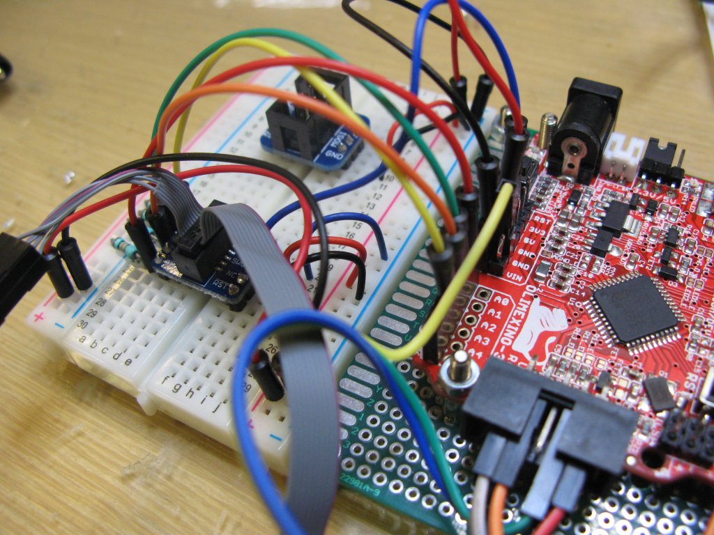
Not only did it support  traditional JTAG debugging but also debugWIRE. Atmels own propriety debug protocol aimed at low resource devices such as the ATMega88/168/328 family. I purchased the Atmel ICE basic kit. The kit consists of the Atmel ICE and a 10 pin ribbon cable to 10 to pin JTAG (0.05″ pitch) and 6 pin (0.1″ pitch) SPI connector. The full kit available at a much greater cost shipped with a number of different cables and adaptors. As debugWIRE uses the RESET line for debugging I deemed the 6 pin SPI cable would be all I needed. Or so I thought.

Moving on a few years I find myself now working with the ATmega32U4 again (I needed USB functionality) and to my surprise this device does not support debugWIRE only JTAG. What!!! How can this be?

I was wondering if Atmel sold those additional debug cables separately? Turns out they do but they are almost £50. After shelling out just shy of £100 in the first place I wasn’t prepared to spend another £50 on cables.
adaptor
So I set about building my own adaptor. The main problem I faced was the Atmel have used 0.05″ (1.27mm) pitch connectors rather than the more readily available standard 0.1″ (2.54mm) pitch connectors. What I needed was some form of breakout board or even something to convert from the 0.05″ pitch connector to something more manageable. After trawling the net it turns out Adafruit have a Cortex SWD adaptor which in essence is a 0.05″ pitch to 0.1″ breakout board. The pin mapping is one to one so assuming you ignore the silk screen it should be easy to interface to the ATmega32U4. The best thing about this solution is the price, I managed to get two of these boards from a local supplier for just £3.

The development board I am currently using is an OLIMEXINO-32U4 an Arduino Leonardo type design from Olimex. The table below shows the Cortex SWD to AVR JTAG pin mapping. Also shown is the JTAG connections of the 32U4 (or Arduino Leonardo if you prefer) development board.

# SWD Pin JTAG Pin Olimex 32u4 Pin
1 Vin TCK A3 (PF4)
2 SWIO GND GND
3 GND TDO A1 (PF6)
4 CLK VCC VCC
5 GND TMS A2 (PF5)
6 SWO RESET RESET
7 KEY N/C N/C
8 N/C N/C N/C
9 GND TDI A0 (PF7)
10 /RST GND GND

Below you can see a picture of my setup. I am not sure if they are needed but I did add 10K pull ups to all of the control lines TCK, TDO, TMS and TDI.

board1

One thing that had not dawned on me was the fact JTAG is not enabled by default. The pins designated to the JTAG interface PF4-PF7 are used as analog inputs. So in order for JTAG to work you need to ensure the JTAGEN fuse is programmed. This can be done through the ISP interface in the normal manner. Once I had that programmed I could successfully download and debug my code on target. Result.

Raspberry Pi Internet Radio

I am a big fan of internet radio stations but it can be a bit restricting listening to my favourite stations on my laptop or phone. So over the last couple of weeks I have been building my own internet radio. A lot of people have converted old routers into radios but the best example I found was Bob Rathbones amazing Raspberry PI Radio. I had an old Raspberry Pi 2 lying around not doing much so I decided why not give it a try. Bob provides on his website an extremely comprehensive guide that takes you through the process of building an internet radio which if you’re interested you can download here.

At the heart of this radio is Music Player Daemon (MPD) running on Raspian Jessie. MPD is a flexible, powerful, server-side application for playing music. Through plugins and libraries it can play a variety of sound files while being controlled by its network protocol. Bobs manual provides a detailed overview of construction and software. It contains instructions for building the radio using either the HDD44780 LCD directly wired to the Raspberry PI GPIO pins or alternatively using an either an Adafruit RGB-backlit LCD plate or the PiFace Control and Display (CAD) . An I2C backpack is also now supported. It can be constructed using either push buttons or rotary encoders. An optional infra-red remote control can also be used. Along with the construction guidelines Bob also provides software to drive the LCD, read the switch states and interface with the MPD server.

When I started I had a pretty good idea of what I wanted to achieve with this radio. I wanted a 4×20 HDD44780 based LCD display, push buttons for control (rather than rotary encoders) and a pair of 4″ coaxial speakers. I wanted it to sound as good as possible so decided early on to use a Digital to Analogue Converter (DAC) rather than relying on the line level audio output on the Pi. A network connection would be via WiFi rather than a LAN connection. It would also have the ability to play music from an external USB device. Possible even the ability to control it with an old infra-red remote control.

The enclosure was constructed from 9mm MDF sheet. The dimensions of which were based around the two coaxial 4″ speakers and the LCD display. I didn’t want anything too big but I also didn’t want it so cramped inside that everything wasn’t going to fit.

enclosure2.Using Front Panel Designer I drew up a template to aid with the drilling of the holes for the speakers, the switches and the panel cut out for the display. The whole thing was then glued and joined with furniture blocks before being painted.

While in my local Maplin store I managed to bag a pair of 4″ Vible Slick Coaxial speakers from their clearance section for a good price. They fitted the bill perfectly. The speakers are driven via a 2x30W audio power amplifier kit from Velleman. The amplifier has an RMS output of 15W into 4 ohms and is protected against overheating and short circuits. The LCD display is driven directly by the GPIO lines of the Raspberry Pi. As are the switch inputs. inside3aIn order to minimise the wiring somewhat I built a little interface board between the display, the switches and the header on the Raspberry Pi. I added a small potentiometer to the interface board to allow the overall volume to be configured.

Power for the Raspberry Pi is provided by the official mains power supply while the amplifier is powered via a 12V 50VA toroidal transformer. As I have already mentioned I wanted the radio to sound the best it possibly could so I opted to use the HifiBerry DAC+, a little expensive costing nearly as much as the Pi itself but it was definitely worth it. I am no audiophile but when driven hard those 4″ speakers sound great. With the addition of a panel mount USB socket music can also be played from a USB device.

Total spend is probably approaching well over £100, even already having the Raspberry Pi, but I am really pleased with the result. I have now have a fully up-gradable internet radio with around 600 stations configured that I can control remotely and sounds and looks amazing.

LG 32LC56 Power Supply Repair

I recently inherited a completely dead LG 32″ LCD TV from my parents. Apparently this TV set was working fine one day and completely dead the next. So I thought I would have a look and see if I could get it back up and running. Upon receiving the set the first thing I did was try and power it up. Nothing completely dead. No standby light nothing. Checked the fuse in the plug (obviously) and that was fine. Time to dig a bit deeper.

With the current symptoms the obvious suspect is going to be the power supply. The internet is strewn with examples of power supplies going bad in these TVs and people on eBay are even selling repair kits for anyone wanting to repair them.

After carefully removing the back panel I had managed to expose the power supply board. I must say a bit of a beast by all accounts. But if you think about the job it has this is to be expected. Fortunately most of the connectors were labelled with the expected output voltages. Probing around on these pins showed no voltage on any of them. Checking the mains into the board gave a reading of around 230V AC. Checking the voltage after the 5A fuse on mains input read nothing. Turns out this fuse had blown. Question is why?

On closer inspection smoke damage can be seen on the large heat sink holding the power transistor, bridge rectifier and rectifier diode on the input stage. My first thoughts were one of these may have been damaged but on closer inspection it turns out the smoke was caused by a 220 pF 2Kv ceramic disc capacitor just in front of the heat sink (shown in the image above directly between the transformer and the heat sink) exploding. Which explains why the fuse may have blown. Probing around the remainder of the input stage the other components appeared to be fine as far as I could tell. Turning my attention to the electrolytic capacitors (shown above) on the output stage I could immediately see a number of these were starting to show the tell tale signs of failure with at least three of them having significant bulging. So I decided I would replace all of them just as a matter of course along with the ceramic disc capacitor that had blown.

Once all of the new components had arrived and been fitted along with a new fuse I powered up the board on the bench and now had a 5V standby voltage present. After fitting the board back into the TV and a quick press the power button on the side and the TV sprung back into action. Result. So a nice easy fix this one. Total spend was about £3 whereas a refurbished power supply board runs to around £30. And for a TV only worth probably that in the first place it hardly seems worth it.

Build a Performance Quadcopter for under £150 – Part 2

I would like to start off by saying thank you to HobbyKing for their extremely prompt service. I now have in my possession a cardboard box full of quadcopter parts. I wasn’t going to waste any time getting started.

The first task was to assemble the frame. The frame consists of two glass fibre plates, an upper and lower plate, as well as four coloured plastic arms, two red and two white. How you configure of these arms is entirely up to you. I decided I would have the two white arms pointing forwards while the red arms pointed backwards. Attaching the arms is simply a case of screwing them to each plate with the screws provided. I found it easier to attached the arms to the lower plate first before adding the upper plate. If your following along with your own build be careful not to over tighten these screws and I would suggest investing in a decent set of hex drivers before starting.

With the frame assembled I then moved on to attaching the motors. This was simply a case of lining the up the holes on the motor with the holes at the end of each arm and using the screws provided with the frame to secure them in place.

Keeping this post short because I have run out of time for now. Next up I will be preparing the speed controllers and flashing them with Simon K’s modified firmware. So stay tuned.

Build a Performance Quadcopter for under £150 – Part 1

With summer fast approaching I decided it was high time I started a new project. I have been toying with the idea of building a quadcopter for a while now. The internet is littered with websites and videos detailing other people’s builds so I decided to give it a go. What will follow hopefully is a number of successive posts detailing my build process. Which should provide enough instruction for other people to build their own.

From the outset I had a fairly rough idea of what I wanted to achieve but for a little more inspiration I started reading a other peoples builds. One if the best builds I found was from a chap named Daniel J. Gonzalez. He based his quadcopter around a 330 mm frame which seemed like a good compromise to me. Click on the picture below to jump directly to the build on his blog.

Daniel J. Gonzalez My First Quadrotor

Daniel J. Gonzalez’s My First Quadrotor.

Like Daniel I opted to use the Hobby King F330 glass fibre frame. For the flight controller I decided on the Hobby King KK2.1.5 based purely on the customer reviews. Apparently the KK is easy to set-up and flies exceptionally well. It may well do with a competent pilot but time will tell how it copes with me in control. The speed controls I chose were the Hobby King blue series controllers. These are a fairly standard controllers however they can be flashed with Simon K’s high performance firmware optimized for quadcopter use. More on this later. The motors were Turnigy 1100kV outrunners which I am hoping should produce more than enough thrust to get the quadcopter off the ground and maybe even enough to carry a GoPro in the future.

The complete shopping list is shown below:-

Part Quantity Cost ($)
Glass Fiber Mini Quadcopter Frame 330mm 1 11.75
D2822/17 Brushless Outrunner 1100kv 4 20.00
Hobbyking KK2.1.5 Multi-rotor LCD Flight Control Board 1 19.99
HobbyKing 20A BlueSeries Brushless Speed Controller 4 39.40
GWS Style Slowfly Propeller 8×4.5 Black (CW) (4pcs) 1 2.63
GWS Style Slowfly Propeller 8×4.5 Black (CW) (4pcs) 1 2.62
Turnigy High Quality 14AWG Silicone Wire 1m (Red) 1 1.56
Turnigy High Quality 14AWG Silicone Wire 1m (Black) 1 1.56
Turnigy High Quality 18AWG Silicone Wire 1m (Red) 1 0.60
Turnigy High Quality 18AWG Silicone Wire 1m (Black) 1 0.80
10CM Servo Lead (JR) 32AWG Ultra Light 1 2.46
PolyMax 3.5mm Gold Connectors 10 PAIRS 2 4.20
Turnigy 4mm Heat Shrink Tube 1M (Red) 1 0.85
Turnigy 4mm Heat Shrink Tube 1M (Black) 1 0.73
Turnigy 5mm Heat Shrink Tube 1M (Red) 1 0.77
Turnigy 5mm Heat Shrink Tube 1M (Black) 1 0.68
Nylon XT60 Connectors Male/Female 1 3.92

Total spend = $114.52 + $8.09 (shipping) = $122.61 which was approximately £89.42 GBP at the time of purchase. All that was required to complete the build would then be a suitable 3S LiPo battery pack and radio system. I hadn’t decided on which radio system to use so opted to leave that until the initial build was complete.

Parts on order so the next post I shall start the build process.

GPS Data Logging

Over the last few weeks I have been playing with a couple of U-Blox NEO-6 Global Positioning System (GPS) receivers I purchased from eBay. What I love about these receivers is they are extremely easy to use. Once powered is applied the receiver starts outputting positional information. The two receivers I have both use a UART interface. However I believe the chip set does support other interfaces including SPI and USB.

Support for these receivers from U-Blox is second to none. As well as a comprehensive manual U-Blox also provide free evaluation software known as U-Center which allows you to evaluate and test these modules in real time. The receivers may also be configured using U-Center.

By the time I received the receivers I already had a couple of projects I wanted to use them for. First off I wanted to build a standalone GPS display device similar to the Quanum GPS Logger V2. The main use for these appears to be for carrying out speed runs of radio controlled cars and planes. Although not massively expensive I figured it would be much more fun to build something similar rather than going out and buying one.

Secondly I wanted a dedicated GPS logging device. As I keen cyclist I am regularly out and about on my mountain bike and often find myself off the beaten track in the middle of nowhere. What would be nice would be the ability to record these routes and import them into Google Earth when I return home. Of course I can track these routes on my phone using Strava or My Tracks but I wanted something a bit more robust. Something I wasn’t overly worried about getting damaged.

Reinventing the Wheel

As I have already mentioned the NEO-6 receivers output positional information via a serial interface. They support two protocols a propriety binary protocol and the National Marine Electronics Association (NMEA) standard. The NMEA standard uses a simple ASCII protocol to send sentences to listening devices. The typical baud rate for this protocol being 4800 baud however my receivers came preconfigured to use 9600 baud. The default update rate for these receivers is every second which is more than adequate for logging purposes.

When it comes to importing this information fortunately Google Earth is now able to import NEMA logs directly without the need for conversion. In the past NEMA logs would have to have been converted to Keyhole Markup Language (KML) format in order to use them with Google Earth. Thankfully this is no longer the case.

So with the receiver continually outputting NMEA messages all that was required was the ability to capture these messages and save them to external media. Now there is no point reinventing the wheel and I figured there must be a whole host of data loggers out there cable of logging serial data. Sparkfuns OpenLog seemed like the ideal solution. OpenLog is an open source Arduino based data logger. Running on an ATMega328 micro controller OpenLog stores received data to an external microSD card. Cards up to 64GB are supposedly supported.

Rather than buying an OpenLog module I built one using a Arduino Nano and a microSD card breakout board. Worked out a lot cheaper in the end. The serial output from the GPS receiver was then fed directly into the Arduino Nano UART RX pin. I did make one minor change to the original OpenLog sketch. By default OpenLog creates new files with the “.TXT” extension. I changed this to “.LOG” which is file type Google Earth is looking for when importing logs. The device is powered via the USB connector, I have it attached to a portable USB power bank at the moment.

logger

I have done a couple of test runs with it and it works great I have logged a couple of bikes rides as well as a 300 miles round trip in the car. All of which imported into Google Earth perfectly. All that remains is to get it into a suitable enclosure.


Driving OLED Displays

In a recent project I used a small 128×64 pixel OLED display module. These modules are great because the provide a clear and vivid display while requiring no back lighting. The display I used had a Systech SSD1306 controller fitted. The internet is rife with examples of code for driving these displays so I had it up and running with fairly minimal effort.

Having decided to use these displays on another project I am currently working on I found them on the R/C model site HobbyKing. Turns out the MultiWii flight controller (Arduino based flight controller originally using gyroscopes and accelerometers from the Wii controllers) uses an add-on OLED display module which no surprise features a 128×64 OLED display driven but the SSD1306 controller. As I was already ordering from Hobby King I decided to bundle one in with my order.

When the display arrived I assumed since both modules used the same display drivers the code I had already written would work out of the box. Wrong! Come on things are never that simple. Time to start investigating. First thing was to look at the two displays see how they compare. One thing that strikes you straight away is the lack of components on the new display (yellow PCB) compared with the old display (blue PCB).

Working_labelledWorking display module.
Not_Working_labelled

Not working display module.

Next step was to start reading the data sheet to see how this controller is configured. The pin out for the connections to the display can be seen below. I have also labelled them on the pictures above.

Pin Connection Description
1 N/C No connection. (GND)
2 C2P Charge pump capacitor.
3 C2N Charge pump capacitor.
4 C1P Charge pump capacitor.
5 C1N Charge pump capacitor.
6 VBAT DC/DC converter supply.
7 N/C No connection.
8 VSS Logic ground.
9 VDD Logic power supply.
10 BS0 Protocol select.
11 BS1 Protocol select.
12 BS2 Protocol select.
13 CS Chip select.
14 RESET Driver reset.
15 D/C Data/Command select. In I2C mode, this pin acts as SA0 for slave address selection.
16 R/W Read/Write.
17 E/RD Enable Read/Write.
18 D0 Input/output. When I2Cmode is selected, D0 is theserial clock input SCL.
19 D1 Input/output. When I2Cmode is selected, D2 & D1 should be tired together andserve as SDAout & SDAin.
20 D2 Input/output.
21 D3 Input/output.
22 D4 Input/output.
23 D5 Input/output.
24 D6 Input/output.
25 D7 Input/output.
26 IREF Brightness current reference.
27 VCOMH COM signal high voltage. A capacitor should be connected between this pin and VSS.
28 VCC OEL panel power supply. A stabilization capacitor should be connected between this pin and VSS when the converter is used.
29 VLSS Analog ground.
30 N/C No connection. (GND)

The controller has an internal charge pump regulator circuit for generating the 7.5V required by the display. Two external capacitors are required. These are connected between C1P/C1N and C2P/C2N and can be seen on both displays.

Both VCC and VCOMH have decoupling capacitors down to GND as outlined in the data sheet. The brightness current is set by the resistor between IREF and GND. The working display using 910K while the non working display opting to use 560K. The 3.3V regulator provides the required logic voltage.

Interestingly it turns out the controller supports communication over I2C, SPI (3 and 4 wire) and parallel. The protocol selection pins BS0-BS2 allow different protocols to be selected. Both displays have BS0 and BS2 are tied to GND while BS2 is tied to the positive supply which as expected sets the mode to I2C.

When configured for I2C mode D0 acts as the serial clock input. The data sheet stipulates that D1 and D2 should then be connected together to act as the serial data line. On closer inspection of both displays it becomes apparent this is the case the working display (blue PCB) but not with the non working display (yellow). Another thing the working display appears to have pull up resistors connected to SCL and SDA. Something you would expect with I2C comms. The non working display has no pull ups fitted.

Having said that the non working display appears to have three unpopulated foot prints on the PCB allowing for pull resistors to be fitted and for D1 and D2 to be connected together. So the first I did was to add and a zero ohm link between D1 and D2 joining them together. I didn’t bother with any pull up resistors. After fitting the display back into my development board and powering up to my surprise it worked!!

I can only assume when configured for I2C operation D1 acts as the serial input to the controller while D2 acts as the output. Joining the two must allow the acknowledge bit set by the controller to be read by the driver. The driver could have been modified to remove the need for the acknowledgement but this would have meant changing the code to be device specific which I didn’t want to do.

One nice feature on the old display is the ability to change the slave address. In I2C operation the Data/Command pin can be configured to set the lowest bit of the slave address SA0. Allowing the slave address to be either 0x78 or 0x7A. Meaning more than one display could fitted on the same bus.

Another slight gripe is the lack of power on reset circuitry on the new display. The working display has a simple reset circuit comprising R1, C1 and D9. The RC network ensures the reset pulse is present while the supply voltage rises keeping the controller in reset while the supply stabilises. D9 allows C1 to quickly discharge on power down in order to generate a reset pulse on power up in the case of short power downs or spikes. Having the reset pin tied directly to the supply, in the case of the new display, means the reset pin will rise of the same rate as the supply which is not ideal. The track could be cut and a reset circuit added but since it worked I wasn’t going to start modifying it.


TM1638 Seven Segment Display Driver with Key Scan Interface

While looking for a new display on eBay recently I stumbled across a seven segment display module. The module (shown below) features 8 seven segment displays, 8 push button switches as well as 8 LEDs. All of which are controlled by one single driver IC the TM1638. I have never come across the TM1638 before, I have used similar display driver ICs like the MAX7219, but never the TM1638.

led_key

After some googling I discovered the TM1638 is manufactured by a Chinese outfit known as Titan Micro Electronics. After downloading the data sheet I begun looking to see how this driver is used. At this point I must state the data sheet, which appears to have been translated from chinese to english, badly, leaves a lot to be desired. Fortunately for me the Arduino fanboys seem to love these devices and there is no shortage of information scattered across the internet. So armed with this information I decided to purchase one.

Once it had arrived getting it working was fairly straight forward. The module does not come with schematic and I wasn’t going to bother reverse engineering the board to create one (not unless I ran into any issues I could not resolve) so it was a bit trial and error in the early stages. In the rest of the post I will demonstrate how to use this device in more detail.

Background

The TM1638 is a LED driver controller with integrated key-scan interface. Communication with the device is via a 3 wire serial interface. The device is capable to of driving up to 8 x 10 LED segments. As well as reading 24 individual key inputs. The display intensity of the LED segments can also be dynamically configured.

Connections

The supply voltage for the device is quoted as 5V ±10% however have seen evidence of people using a 3V3 supply and not having issues.

The LED segments are connected to the device via the segment output pins SEG1-SEG10 and grid output pins GRID1-GRID8. The module I purchased has 8 seven segment displays and a further 8 LEDs. These seven segment displays connect via segment output pins SEG1-SEG8 and grid output pins GRID1-GRID8. The 8 LEDs connect via segment output pin SEG9 and grid output pins GRID1-GRID8.

Image17

The push button switches are multiplexed together and read via key state output pins KS1-KS8 and key scan data input pins K1-K3. Note key state output pins KS1-KS8 share the same physical pins as the segment output pins SEG1-SEG8. The device simply alternates between driving the segment outputs and scanning the key input states.

Communication with the device is via a 3 wire serial interface comprising of a strobe (STB), data input/output (DIO) and a clock (CLK) pin. The strobe pin is used to initialise the serial interface prior to sending data. The state of the DIO pin is clocked into the device on the rising edge of the clock signal. Similarly when reading from the device the state of DIO pin may be read on the rising edge of the clock signal.

Image31

Operation

The protocol used to communicate with the TM1638 is a fairly simple one. The transfer is initialised by first pulling the strobe line low, a command byte is then sent followed by a number of optional arguments. The transfer is then terminated by returning the strobe pin high. Each command sent must begin with the strobe pin being pulled low and finish with the strobe pin being pulled high.

The device supports three command types. Determined by bits B7 and B6 of the command byte. Data instruction set 0b01 (0x4X) writes or reads data to or from the device. Display control instruction set 0b10 (0x8X) configures the device and Address instruction set 0b11 (0xCX) sets the display register address.

Image23

The first thing we want to do post power up is initialise the display. To do so we need to send the display control instruction set command 0x8X.

Image13

The table above shows the individual bit settings for this command and their relevant function. Bits B7 and B6 set the command type, fixed at 0b10 (0x8X). Bits B5 and B4 are irrelevant and set to 0b00. Bit B3 is used to turn the display ON (1) or OFF (0). The remaining bits B2, B1 and B0 configure the display intensity. They actually set the pulse width which determines the display intensity. 1/16 (0x00) being the dullest and 14/16 (0x07) being the brightest.

For instance if we wanted to turn the display ON with the intensity set to maximum we would send the command 0b10001111 (0x8F). For minimum intensity we would send the command 0b10001000 (0x88).

The data instruction set command can perform a number of functions. We can set the data write mode to either write data to a data register or read the key scan data. We can set the address add mode to either automatically increment the destination address while writing data or write to a fixed destination address. There is also a test mode set function which we will not cover here.

Image24

Bits B7 and B6 set the command type and are fixed at 0b01 (0x4X). Bits B5 and B4 are irrelevant and set to 0b00. Bit B3 is used to set the test mode which we will keep set to 0 normal mode. Bit B2 sets the address add mode (0 automatically increments the address and 1 sets a fixed address). Bits B1 and B0 set the data write mode to be either a write to a data register (0b00) or read from the key scan data register (0b10).

The address instruction set command configures the destination address/register we wish to write. There are 16 display registers in total. Bits B7 and B6 set the command type and are fixed at 0b11 (0xCX). Bits B5 and B4 are irrelevant and set to 0b00. The remaining bits B3, B2, B1 and B0 set the display address (0x00 through 0x0F). The data stored in these registers is used to drive the display segments. Which we will cover in more detail soon.

Image27

This may all look very confusing so let’s cover a couple of examples which should make things a little clearer. Let’s say we want to send the value 0x45 to display register 0x02. The address mode will be fixed since we are only writing one register. So we send the command 0x44 (0b01000100) followed by command 0xC2 (0b11000010) followed by 0x45. If we wanted to send the values 0x01, 0x02 and 0x03 to display registers 0x00, 0x01 and 0x02. The address mode will be set to auto increment since we are writing consecutive registers. We would then send the command 0x40 (0b01000000) followed by command 0xC0 followed by 0x01, 0x02 and 0x03.

To read the state of the keys we need to send the command 0x42 (0b01000010) before reading back 4 bytes containing the key states. The details of which we will cover in more detail further on.

As already mentioned the display registers allow us to set all of the individual segment states. The mapping of each segment in the display registers can be seen in the table below.

Image6

For instance segment output pins SEG1-SEG8 which control the seven segments (A-G) plus the decimal point (DP) on grid output pin GRID1 are mapped to display register 00HL (the lower 4 bits of the display register 0) and 00HU (the upper 4 bits of the display register 0). The remaining two segment output pins SEG9 and SEG10 are mapped to the lower two bits of display register 01HL. The remaining bits of display register 1 have no function. This is then repeated for digit 2 using registers 02HL/02HU and 03HL/03HU etc.

The module I have has single LEDs all connected to segment output pin SEG9 and no connections to segment output pin SEG10. Some of the modules available on eBay have bi-colour LEDs on which I assume SEG9 is used to drive one colour and SEG10 to drive the other.

Again this may appear somewhat confusing so let’s have another example. Let’s say we wanted to show ‘0’ on display digit 1. In order to show ‘0’ we need to set segments SEG1 (a), SEG2 (b), SEG3 (c), SEG4 (d), SEG5 (e) and SEG6 (f) while segments SEG7 (g) and SEG8 (DP) remain unset. We do this by loading display register 0 with the value 0b00111111 (0x3F). For display digit 2 we load display register 2 with 0b00111111 (0x3F) etc.

digits

Similarly if we wanted to energise the LED1 we would need to set SEG9 by loading display register 1 with 0b0000001 (0x01). For the LED2 we would load display register 3 with 0b0000001 (0x01) etc.

When it comes to reading the input keys. A maximum of 24 keys may be read by the device. These are all arranged in a 3×8 matrix format. The key states returned from the read key scan data command as four bytes encoded as follows.

Image10

BYTE1 contains the key input states K3 (B0), K2 (B1) and K1 (B2) for key state output KS1 and K3 (B4), K2 (B5) and K1 (B6) for key state output KS2. BYTE2 corresponds to key state outputs KS3 and KS4. BYTE 3 corresponds to key state outputs KS5 and KS6 and BYTE4 corresponds to key state outputs KS7 and KS8. Bits B3 and B7 in all four bytes are irrelevant and are ignored.

For example to read the input state of the key corresponding to input state K2 and key state output KS8 we read bit B5 of BYTE4. To read the input state of the key corresponding to input state K3 and key state output KS1 we read bit B0 of BYTE1.

After a bit of trial and error I discovered the eight keys on my board are all mapped to input state K3. So by checking bits B0 and B4 of each of the 4 bytes read I was able to determine the state of all of the 8 keys.

I have created a basic driver for the TM1638 (written in C) using Atmel Studio. The driver has been tested on a ATMega328 (Arduino Nano) development board. However the code could easily be ported to any other platform if required. All of the project files and an example implementation are all available on my GitHub account.