Category Archives: Retro Computing

Stellaris Mod Player V2

After having issues with the latest version of Code Composer Studio from TI I decided to port this project over to Keil uVision instead. While doing so I took the opportunity to tidy up the code and add a few new features.

One such feature is auto play next module. If enabled next module in the list will play automatically. Auto play is enabled by simply placing a empty file named “autoplay.dat” in the mods folder of the SD card which is detected during power up.

Auto play WILL NOT work with all modules. To detect the end of the module has been reached the code looks for the point where the playback index equals the total song length which would normally roll back to the start of the module. If the composer has used JUMPTOORDER the module may never reach the end. There is no way to determine if the jump is legitimate or the end of the module has been reached.

Source and project files compatible with Keil uVsion V5 are all available in my GitHub account along with pre built images in binary and hex format.


Arcade Controller Conversion…Part 2

arcade2
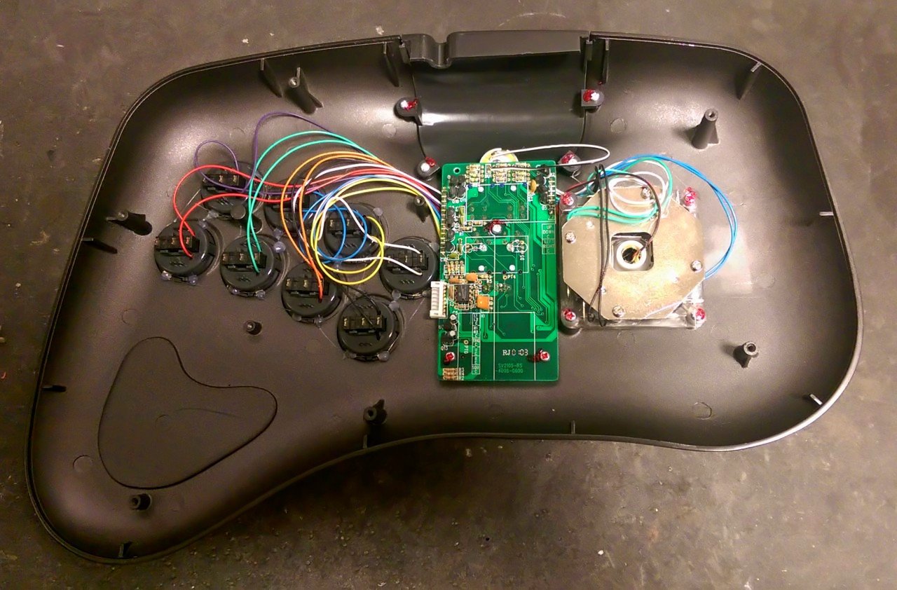
With the case now modified to fit the new joystick and buttons I moved onto the interface board. Rather than buying one I decided from the onset that I was going to design my own. Those you buy of the shelf in my opinion are just way overpriced for what you get. The majority of which are keyboard encoders. All I needed after all was a simple joystick to USB converter with support for up to eight buttons. The design I came up with encompasses a Minimus AVR development board I already had lying around. These boards are ideal for USB projects. They feature an Atmel  AT90USB162 micro controller with full speed USB controller which makes implementing USB applications a breeze. For the firmware I opted to use the LUFA (Lightweight USB Framework for AVRs, formerly known as MyUSB). I have used LUFA a lot in recent years because I find it extremely easy to implement as well as being extremely well documented.

arcade_controllerWith the design laid out on strip board I started on the firmware. Rather than starting from scratch I took the joystick class driver example provided with the LUFA and begun modifying it to suit my needs. The example project implements a Human Interface Device (HID) class joystick driver. Since most operating systems support the USB HID classes out of the box there is no need for any third party drivers. Within the project is a call back function used to create the HID report to be transferred to the host. All that was needed was, during the call back function, to read the joystick and button states and add them to the generated report. The main USB call would then take care of transferring this report to the host.

 bool CALLBACK_HID_Device_CreateHIDReport( USB_ClassInfo_HID_Device_t* const HIDInterfaceInfo,  
                                           uint8_t* const ReportID,  
                                           const uint8_t ReportType,  
                                           void* ReportData,  
                                           uint16_t* const ReportSize)  
 {  
      /* New joystick report */  
      USB_JoystickReport_Data_t* JoystickReport = (USB_JoystickReport_Data_t*)ReportData;  
      /* Get joystick states */  
      uint8_t JoystickStatus_LCL = ( JOYSTICK_PORT_PIN & JOYSTICK_ALL_MASK ) ^ JOYSTICK_ALL_MASK;  
      /* Get button states */  
      uint8_t ButtonStatus_LCL = ( BUTTONS_PORT_PIN & BUTTONS_ALL_MASK ) ^ BUTTONS_ALL_MASK;  
      /* Check joystick Y axis */  
      if( JoystickStatus_LCL & JOYSTICK_UP_MASK ) JoystickReport->Y = -100;  
      else if( JoystickStatus_LCL & JOYSTICK_DOWN_MASK ) JoystickReport->Y = 100;  
      /* Check joystick X axis */  
      if( JoystickStatus_LCL & JOYSTICK_LEFT_MASK ) JoystickReport->X = -100;  
      else if( JoystickStatus_LCL & JOYSTICK_RIGHT_MASK ) JoystickReport->X = 100;  
      /* Check joystick buttons */  
      if( ButtonStatus_LCL & BUTTONS_BUTTON1_MASK ) JoystickReport->Button |= (1 << 0);  
      if( ButtonStatus_LCL & BUTTONS_BUTTON2_MASK ) JoystickReport->Button |= (1 << 1);  
      if( ButtonStatus_LCL & BUTTONS_BUTTON3_MASK ) JoystickReport->Button |= (1 << 2);  
      if( ButtonStatus_LCL & BUTTONS_BUTTON4_MASK ) JoystickReport->Button |= (1 << 3);  
      if( ButtonStatus_LCL & BUTTONS_BUTTON5_MASK ) JoystickReport->Button |= (1 << 4);  
      if( ButtonStatus_LCL & BUTTONS_BUTTON6_MASK ) JoystickReport->Button |= (1 << 5);  
      if( ButtonStatus_LCL & BUTTONS_BUTTON7_MASK ) JoystickReport->Button |= (1 << 6);  
      if( ButtonStatus_LCL & BUTTONS_BUTTON8_MASK ) JoystickReport->Button |= (1 << 7);  
      /* Set report size */  
      *ReportSize = sizeof(USB_JoystickReport_Data_t);  
      return false;  
 }  

Every USB device must contain an embedded device descriptor which describe to the host information such as what the device is, who makes it, what version of USB it supports etc. This device descriptor contains a vendor ID (a 16-bit number) which is assigned by the USB Implementers Forum to a specific company. Who in turn assign a product ID (again a 16-bit number) to individual products. In the case of the LUFA joystick example the vendor ID and product ID used are 0x03EB and 0x2043 respectively. Refering to the USB ID Repository on the Linux USB home page shows the registered vendor ID as “Atmel Corp.” (no surprise there) and the product ID as “LUFA Joystick Demo Application”. The VID and PID are communicated to the computer when the device is plugged in, along with text strings describing the vendor and product as well as additional descriptors. I choose to modify these vendor and product strings to something more meaningful to me.

output_BGcEfUWith the code compiled and programmed into the AT90USB162 the first test was to check it worked under windows. Once plugged in windows identified the device and installed a suitable driver. Then using the game controllers configuration wizard I was then able to confirm the joystick and buttons were functioning correctly.

Moving on time to start testing on the Raspberry Pi. RetroPie detected the controller and allowed it to be configured for use. This is fine for navigating the RetroPie front end but in order to use it with any of the emulators (apart from MAME who has its own set-up) the controller needs registering for use with RetroArch. So exiting RetroPie and checking available USB devices shows the device has been detected on bus 001 device 005. The vendor ID and product ID clearly shown.

 Bus 001 Device 002: ID 0424:9512 Standard Microsystems Corp.  
 Bus 001 Device 002: ID 0424:9514 Standard Microsystems Corp. 
 Bus 001 Device 001: ID 1d6b:0002 Linux Foundation 2.0 root hub
 Bus 001 Device 003: ID 0424:ec00 Standard Microsystems Corp. 
 Bus 001 Device 004: ID 7392:7811 Edimax Technology Co., Ltd EW-7811Un 802.11n Wireless Adapter [Realtek RTL8188CUS]
 Bus 001 Device 005: ID 03eb:2043 Atmel Corp. LUFA Joystick Demo Application 

Then registering the controller for use with RetroArch using the “Register RetroArch controller” script. You can see the modified manufacturer and product strings read by the script.

  Using joypad: Mikes Modz Arcade Controller  
 Joypads tend to have stale state after opened.  
 Press some buttons and move some axes around to make sure joypad state is completely neutral before proceeding.  
 When done, press Enter ...   
 Configuring binds for player #1 on joypad #0.  
 B button (down)  
      Joybutton pressed: 0  
 Y button (left)  
      Joybutton pressed: 1  
 Select button  
      Joybutton pressed: 2  
 Start button  
      Joybutton pressed: 3  
 Up D-pad  
      Joyaxis moved: Axis 1, Value -32767  
 Down D-pad  
      Joyaxis moved: Axis 1, Value 32767  
 Left D-pad  
      Joyaxis moved: Axis 0, Value -32767  
 Right D-pad  
      Joyaxis moved: Axis 0, Value 32767  
 A button (right)  
      Joybutton pressed: 4  
 X button (top)  
      Joybutton pressed: 5  
 L button (shoulder)  
      Joybutton pressed: 6  
 R button (shoulder)  
      Joybutton pressed: 7  
 L2 button (trigger)  
      Timed out ...  
 R2 button (trigger)  
      Timed out ...  
 L3 button (thumb)  
      Timed out ...  
 R3 button (thumb)  
      Timed out ...  
 Left analog X+ (right)  
      Timed out ...  
 Left analog X- (left)  
      Timed out ...  
 Left analog Y+ (down)  
      Timed out ...  
 Left analog Y- (up)  
      Timed out ...  
 Right analog X+ (right)  
      Timed out ...  
 Right analog X- (left)  
      Timed out ...  
 Right analog Y+ (down)  
      Timed out ...  
 Right analog Y- (up)  
      Timed out ...  
 Writing autoconfig profile to: /opt/retropie/emulators/retroarch/configs/tempconfig.cfg.  
 input_player1_joypad_index = "0"  
 input_player1_b_btn = "0"  
 input_player1_y_btn = "1"  
 input_player1_select_btn = "2"  
 input_player1_start_btn = "3"  
 input_player1_up_axis = "-1"  
 input_player1_down_axis = "+1"  
 input_player1_left_axis = "-0"  
 input_player1_right_axis = "+0"  
 input_player1_a_btn = "4"  
 input_player1_x_btn = "5"  
 input_player1_l_btn = "6"  
 input_player1_r_btn = "7"  
 = = = = = = = = = = = = = = = = = = = = =  
 Configuring RetroArch-AutoConfigs  
 = = = = = = = = = = = = = = = = = = = = =  
 Remapping controller hotkeys  
 Processing /opt/retropie/emulators/retroarch/configs/2Axes11KeysGamePad.cfg  
 Processing /opt/retropie/emulators/retroarch/configs/ControlBlockArcadeGamepad.cfg  
 Processing /opt/retropie/emulators/retroarch/configs/ControlBlockSNESGamepad.cfg  
 Processing /opt/retropie/emulators/retroarch/configs/DragonRise_Inc.___Generic___USB__Joystick__.cfg  
 Processing /opt/retropie/emulators/retroarch/configs/Generic_X-Box_pad.cfg  
 Processing /opt/retropie/emulators/retroarch/configs/GreenAsia_Inc.____USB_Joystick_____.cfg  
 Processing /opt/retropie/emulators/retroarch/configs/HuiJiaSNEStoUSBConverter.cfg  
 Processing /opt/retropie/emulators/retroarch/configs/JessTechColourRumblePad.cfg  
 Processing /opt/retropie/emulators/retroarch/configs/LogitechGamepadF710.cfg  
 Processing /opt/retropie/emulators/retroarch/configs/LogitechLogitechCordlessRumblePad2.cfg  
 Processing /opt/retropie/emulators/retroarch/configs/Logitech_Logitech_Dual_Action.cfg  
 Processing /opt/retropie/emulators/retroarch/configs/Logitech_Logitech_RumblePad_2_USB.cfg  
 Processing /opt/retropie/emulators/retroarch/configs/Microsoft_Sidewinder_Dual_Strike_USB_version_1.cfg  
 Processing /opt/retropie/emulators/retroarch/configs/Microsoft_X-Box_360_pad.cfg  
 Processing /opt/retropie/emulators/retroarch/configs/MikesModzArcadeController.cfg  
 Processing /opt/retropie/emulators/retroarch/configs/MY-POWER_CO__LTD__2In1_USB_Joystick.cfg  
 Processing /opt/retropie/emulators/retroarch/configs/PS3ControllerBT.cfg  
 Processing /opt/retropie/emulators/retroarch/configs/PS3Controller.cfg  
 Processing /opt/retropie/emulators/retroarch/configs/PS3ControllerUSB.cfg  
 Processing /opt/retropie/emulators/retroarch/configs/RockCandyGamepadforPS3.cfg  
 Processing /opt/retropie/emulators/retroarch/configs/Saitek_P880.cfg  
 Processing /opt/retropie/emulators/retroarch/configs/SNES-to-GamepadDevice.cfg  
 Processing /opt/retropie/emulators/retroarch/configs/Sony_PLAYSTATION(R)3_Controller.cfg  
 Processing /opt/retropie/emulators/retroarch/configs/Thrustmaster_Dual_Trigger_3-in-1.cfg  
 Processing /opt/retropie/emulators/retroarch/configs/THRUSTMASTER_FireStorm_Dual_Analog_2.cfg  
 Processing /opt/retropie/emulators/retroarch/configs/Thrustmaster_T_Mini_Wireless.cfg  
 Processing /opt/retropie/emulators/retroarch/configs/USB_2-axis_8-button_gamepad.cfg  
 Processing /opt/retropie/emulators/retroarch/configs/USB_Gamepad.cfg  
 Processing /opt/retropie/emulators/retroarch/configs/USBGamepad.cfg  
 Processing /opt/retropie/emulators/retroarch/configs/Xbox_360_Wireless_Receiver.cfg  
 Processing /opt/retropie/emulators/retroarch/configs/XboxGamepad(userspacedriver).cfg  

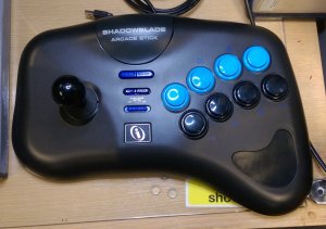
With the controller now registered it was time to start playing. First up Teenage Mutant Ninja Turtles on the SNES which worked great. The Seimitsu joystick has a great feel with lovely movement not too stiff but not too loose either. The buttons respond perfectly with minimal effort, if anything they are little bit to sensitive but that’s fine.

Arcade Controller Conversion…Part 1

I love playing retro arcade games and most recently I have taken to playing these classic games on my Raspberry Pi 2 using the RetroPie. For those who aren’t aware the RetroPie project is a collection of works that all have the overall goal to turn the Raspberry Pi into a dedicated retro-gaming console. Up until now I have been using a couple of cheap USB NES controllers. These controllers are great but nothing compares to the feel of an authentic arcade controller. So I set about building my own controller that could be plugged directly into my Raspberry Pi.

arcade4The first issue would be the enclosure. Do I build something? Or do I buy a flat packed kit from eBay? Neither option was going to be cheap. Then I stumbled on someone selling a second hand PlayStation arcade controller on eBay which at the time was listed at 99p plus postage. I figured that has got to be worth a punt. Even if I can only salvage the case and possibly a few other parts then so be it. So I placed a bid and ended up winning it for just over a pound. Result! I wasn’t expecting a lot but was pleasantly surprised when it arrived. The build quality was a lot better than I had expected. It had obviously seen a fair bit of use and the joystick micro switches were worn out. But still I wasn’t disappointed as the case was in great condition.

arcade5I begun disassembling it as soon as it arrived. I removed the bottom plate, the cable, the joystick and the eight push buttons. I had no plans to use the interface board so I de-soldered all of the connections and left the PCB in situ. Next I measured the holes for the push buttons which turned out to be 30mm which was good news since this a standard size for arcade buttons. Selecting a suitable joystick proved to be more troublesome. There isn’t a lot of clearance for the joystick once mounted so I needed to find one with the lowest possible profile.

In the end I went for a Seimitsu LS-58-01and Seimitsu PS-15 buttons. The LS-58 a great quality small form factor joystick. Not to stiff and with an adequate throw distance for my liking. The micro switches are soldered directly into a PCB. This worked out perfect as I later went on to use the PCB to mount it to the original mounting posts. Being 30mm the PS-15’s fitted perfectly with no modifications required. The joystick however required a few modifications. In order to drill the mounting holes in the PCB I first had to remove the common connections for each micro switch. Rather than completely removing the micro switches I simply cut the tabs and de-soldered. Then after drilling the holes I used Kynar wire to re-connect them.

arcade1The next problem was getting the joystick to fit flush with the case. Because of the way the case had been moulded I needed to remove some of the plastic surrounding the stick. Thankfully this didn’t comprise the rigidity of the joystick. The end result wasn’t pretty but at least it now fitted flush with the case. I finished off by connecting all of the switches to my new interface board which I will move onto in the next post.

There’s life in the old dog yet…Part 3

After a bit of reading around the subject it appears the majority of Amiga video problems are either related to issues with the RAM or the Agnus (Address Generator) chip. The RAM chips are all soldered directly into the board so I re-soldered all of those and still the same issue.

Then I remembered when I first got my brand new Amiga back in the day the first time I plugged it in I had a similar issue. I phoned the computer shop where I had bought it and they said “Its most likely because one of the chips is not seated correctly in its socket. Unplug every thing and hold it flat about two inches above a soft surface (like carpet) and then drop it”. You can imagine my horror. But they assured my if it didn’t work they would replace it with no issues. Much to my relief at the time it worked.

The Agnus chip sits in a 84 pin PLCC socket so I removed Agnus from her socket and set to work re-soldering all of the pins. I reseated Agnus and put everything back into the case before reapplying the power. Much to my relief it appeared to work and since the floppy emulator was still connected it booted straight to the Amiga Pi Drive front end.

Using Maurizios Amiga Pi Drive emulator couldn’t be simpler. The front screen shows a list of all of the ADF (Amiga Disk File) and ADZ (compressed ADF) files found on the SD card. Four floppy drives are shown on the right. The interface only supports drives 0 and 1 (SE0 and SEL1 lines from the motherboard). Drive one may be disabled if you wish to fit a real drive.

Amiga Pi DriveEach drive can be loaded with a number of ADF or ADZ files. The first file in each drive drive will be loaded when emulation is started. For all intents and purposes the Amiga sees a real floppy in this drive and begins to boot it. Pressing the “Change” button loads the next file in the list into the drive. If changes are made on that drive pressing the “Write” will write the contents back to the file on the SD card.

Imgp0746The internet is rife with Amiga emulation sites so finding all my favourite games wasn’t difficult. I downloaded a few I put them on the SD card. Then it was just a case of reminiscing those good old 16 bit classics. I must admit though playing games on my old Cruiser joystick felt a bit alien after playing with modern console controllers. Still the playability of the old Amiga games still win hands down in my opinion.


There’s life in the old dog yet…Part 2

Stop the press. After going down the avenue of replacing the internal floppy drive for a few days (found a couple on eBay but who’s to say these aren’t going to fail in the near future after all these things are over 20 years old) it dawned on me there must be a more up to date solution.

I know some of the later Amiga models the 600 and 1200 featured a 44 pin ATA connector allowing for a 2.5″ internal hard drive to be fitted. And with a suitable connector this hard drive may swapped out for a compact flash (CF) card or I believe even an SD card with the correct hardware upgrade. Unfortunately this is not an option on the old Amiga 500.

The only option appears to be a floppy drive emulator something like Lotharek’s Floppy Drive Emulator. Which allows you to load Amiga Disk Files (ADF) from an SD card or USB mass storage device. Again these are pricey with Lothareks emulator retailing at around 70 euros!!!

So I was toying with the idea of purchasing a second hand drive from eBay when I stumbled upon a floppy emulator a guy (Maurizio Ramondo) had designed for his Amiga 500 using a Raspberry Pi. Like a lot of people I bought a Raspberry Pi when it was first launched. Up until now all its been doing is running Xbox Media Center under my TV.

InterfaceThe Amiga RPI Drive connects GPIO lines from the Raspberry Pi to the Amiga floppy connector via an interface board which takes care of all of the level shifting. The floppy drive I/O being 5V and the Raspberry Pi GPIO being 3.3V. I redrew Maurizios original schematic just for my own benefit. I wanted to have a 26 pin socket so I could connect a ribbon cable from the Raspberry Pi directly to the interface.

The circuit is fairly simple. Each input line is pulled high and then passes through a voltage divider to bring the level down to a more reasonable 3.3V for the Pi. The outputs from the Pi go through a 74LS06 open collector output inverting buffer allowing the signals from the Pi to be pulled up to 5V by the Amiga. The 5V supply voltage is supplied from the floppy drive power connector on the Amiga motherboard. The RDY line is managed directly by the interface and is used to help protect the bus when there are external drives disabling the CHNG line and the DKRD line. The remaining lines are all under software control. The interface only supports two drives since only the SEL0 and SEL1 lines are brought out on the floppy connector. The second line, SEL1 can be disabled via a switch allowing a real external floppy drive to be connected. Maurizio recommends that a Raspberry Pi Model A is used since the Amiga is only able to supply approxitaely 550 mA whereas the Model B he claims draws around 700 mA under certain conditions.

Img_3435Because of the strict timing required to emulate Modified Frequency Modulation (MFM) used by the Amiga floppy drive Maurizio does not use the Linux kernel. Everything was written from scratch. I wont go into any more detail if you want to know more then I suggest you visit his website. Maurizio even provides an SD card containing the kernel and all the files required to boot the Raspery Pi. The SD card even includes a copy Xcopy III allowing you to rip your own disks as well.

The more observant are probably thinking there seems to be a distinct lack of connections. The remaining interconnections are all made underneath the board so the rats nest of wires is hidden from view.

Using the emulator is fairly straight forward too. On power up the emulators front end is loaded. This allows you to queue any number of ADF files into a specific drive. The user then selects the play button and the first disk in drive 0 is loaded. The interface has two switches “change” and “write”. The change switch swaps to the next the disk in the drive. The “write” switch writes any modified disk contents back to the the ADF file on the SD card.

Img_3441After removing the internal floppy drive I was originally going to extend the internal floppy drive and power cable out of the side of the Amiga where the floppy disk slot is. Hence the reason for all of the switches being fitted to the strip board. But after removing the drive it seem to make more sense (space permitting) to mount both the interface board and the Raspberry Pi in place of the original floppy drive. To my surprise it all fitted. I did have to remove the shielding  over the motherboard so I am hoping I don’t have and EMI issues. I then mounted two more push buttons for the “Change” and “Write” functions and a toggle switch for disabling the second drive and fed the connections back to the interface board.

With the interface board completed, the kernel copied to an SD card and everything fitted into the Amiga case I powered everything up. The Pi appeared to power up fine however now all I get on the display is a green screen. Well its too late now so this is going to have to wait for another day. No one said working with these retro machines was going to be easy.


There’s life in the old dog yet

After a recent trip to my parents house and being gently persuaded to take all my old “junk” with me I found my trusty old Amiga tucked away in the loft complete with old boxes of disks. The case had severely yellowed which seems very common with these old computers.

Img_3423

Back in the day I spent my formative teenage years virtually glued to the keyboard of this thing. After the initial infatuation with playing games had worn off I taught myself 68000 assembler and started writing utilities and demos which I guess with the exception of writing a bit of BASIC on my old Amstrad CPC 464 was my first real venture into programming.

So fast forward 20 plus years would it still work ? The first thing I did was take it apart. Just to check everything was still in one piece and check nothing had been damaged. Now being designed when it was all components are through hole. No surface mount in here. Img_3426The majority of the chips are all socketed with the exception of the memory. Everything looks good a bit of dust but that’s about all. Even the battery on the memory upgrade seems to be good a tiny bit of leakage but not enough to have damaged anything.

Initial power up was fine. The red power LED illuminates and the internal floppy starts clicking. So far so good. After connecting the AV-scart lead to my 40″ Samsung LCD TV no picture. Just a white screen. Not good. In the past I had always used an old 15″ Sony CRT TV/monitor which has long gone now. However after rummaging through the box of peripherals I found the original TV modulator. Feeding the composite video from the modulator to a scart-phono adaptor worked just fine. Few so there doesn’t appear to be anything wrong with the Amigas video output stage.

So how am I going to get a decent (ish) picture on a modern LCD TV ? I guess there are a number of options. A lot of people use scan doubler/flicker fixers. Something like the Indivision ECS scandoubler from Amigakit.

Img_3430This simply slots into the video chip (Denise) socket and runs a 15 pin SUB plug to provide VGA output up to 1024×768. There are also a number of scandoublers on eBay that appear to be based on the CGA/EGA/YUV to VGA converters I used in my Weecade arcade machine. Both these options retail for around £80 which is more than I really wanted to spend just to get an old computer up and running.

After a bit more googling I found an article talking about the signal voltages on the video port. It seems these voltages may be too high for most modern TVs. The SYNC signal from the Amiga is apparently around 4.8V peak-peak. Which makes sense if the Amiga is running 5V TTL throughout. Modern TVs expect a synch signal on the composite video or synch on green with a peak voltage of around 1V peak-peak. Since they would probably be operating at 3.3V/1.8V levels. The composite synch input has a 75R terminator which when coupled with a 330R resistor along with the 47R inside the Amiga gives a SYNC voltage of around 1V peak-peak.

So I connected a 330R resistor between pin 10 of the Amiga video port (TTL synch) and pin 20 of the scart lead (composite video). For each of the colour signals Red, Green and Blue I added a 220uF electrolytic just to block any DC bias on those signals. The AV mode signal (pin 8) on the scart was fed from the 12V signal on the video port via 1K resistor. The RGB mode signal (pin 16) was fed from the 5V signal on the video port via a 75R resistor. The logic grounds (pin 13 video port, pin 18 scart) were connected together. The remaining video grounds on each connector were tied together. The audio signals from the scart to two phono plugs was left untouched. Again a couple of small electrolytic capacitors could have been added but I choose not to bother.

After hooking everything backup and firing up the Amiga the iconic start-up screen appeared in all its glory. First hurdle overcome.

With everything up and running I tried booting from the original workbench disk. After inserting the disk the drive starting making some rather strange noises the AmigaDOS screen appeared but then the disk error dialogue appeared soon after. After trying a hand full of other disks it became clear the drive has had its day.

Time to find a replacement internal floppy drive.